Lightning Protection Air Terminals: Size, Height, Spacing and Where They Go
By Site Safe Lightning Protection 9 min read
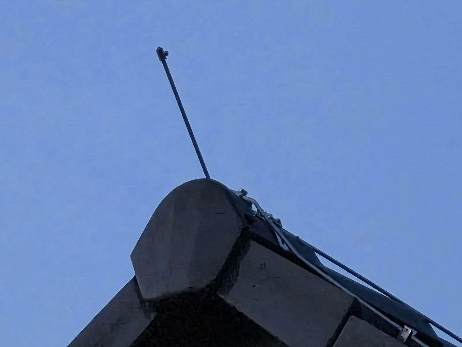
A lightning protection air terminal is a lightning rod. The standards use the longer name, and NFPA 780 groups rods with masts, overhead wires and thick metal bodies under the heading strike termination device. On a US system an air terminal is a solid copper or aluminum rod at least 10 in long, with its tip at least 10 in above whatever it protects, set within 2 ft of the ridge ends and roof corners and then no more than 20 ft apart, or 25 ft apart when 24 in terminals are used (UL guide). Those few numbers decide most of what you see on a roof. The rest of this article explains them, the component rules behind them, and the mistakes inspectors keep finding.
Is an air terminal the same as a lightning rod?
Yes. UL’s marking guide defines an air terminal as a type of strike termination device intentionally installed to receive a strike, and a strike termination device as any metallic component of the system that can take the strike and carry it to the conductors (UL guide). The second definition is wider on purpose. A metal body 3/16 in thick or more that projects above a structure will accept a strike without damage, so it can be bonded in and counted as a terminal (LPI overview). Masts on tank batteries and catenary wires over substations are strike termination devices too. The rod on a house ridge is the plain version.
A terminal doesn’t attract lightning. The National Weather Service’s page on lightning rods is clear that a protection system doesn’t stop lightning from hitting a building. It gives a strike that was going to land anyway a safe route to the ground (NWS).
What UL 96 says a terminal has to be
Components on a certified system are listed to UL 96, the component standard, and installed to UL 96A or NFPA 780. The UL marking guide spells out what a listed terminal and its base look like:
| Item | Requirement |
|---|---|
| Minimum length | 10 in; may be made in parts if longer |
| Minimum diameter | 3/8 in for copper; 1/2 in for aluminum (LPI overview) |
| Attachment | Integral base, or at least five full threads into a separate base; threaded walls at least 1/16 in thick |
| Ornaments | Allowed, but no more than 20 sq in in any plane |
| Bracing | Terminals over 24 in are braced at half their height with a rod of at least 1/4 in, listed for the purpose |
| Base | Stamped (0.097 in aluminum, 0.061 in copper) or cast (at least 3/32 in), with a conductor clamp giving 1-1/2 in of contact on all sides of the cable |
| Class II stacks | Solid copper, copper alloy, stainless, titanium or monel; 18 to 30 in tall; at least 5/8 in diameter; not more than 8 ft apart; no aluminum |
Source: UL guide and LPI overview.
Material choice follows the building. Copper, copper alloy and electrical-grade aluminum are the standard metals. Copper parts within 2 ft of a chimney exhaust are tin coated against flue gases, aluminum is never used where it can touch earth or sit in concrete or masonry, and the two metals aren’t mixed without a bimetallic fitting (LPI specification). The NWS facility standard also allows nickel-plated copper and, in high-corrosion areas, stainless steel (NWSM 30-4106). Our article on what lightning rods are made of goes into Class I and Class II materials.
Blunt or pointed tips
Franklin’s rods were sharp. Most new US systems use rounded tips. The reason is a field study published in 2000 by Charles B. Moore and colleagues at New Mexico Tech, who exposed sharp and blunt rods side by side on a mountaintop and found that moderately rounded or blunt-tipped rods were marginally better strike receptors. Their explanation: the field at a sharp tip is strong but falls off fast, and ionization around the point limits it, so a few centimeters above a 20 mm blunt rod the field is actually stronger (Wikipedia summary of Moore et al.). Existing pointed rods aren’t wrong and don’t need replacing. Many listed terminals now ship with a rounded or safety tip, which also makes them kinder to anyone working on the roof.
Height and spacing rules
The placement rules below come from UL 96A as described in UL’s guide, which tracks NFPA 780. They are what an installer is laying out when they walk your roof with a tape.
| Situation | Rule |
|---|---|
| Tip height | At least 10 in above the protected object or surface |
| Standard spacing | Not more than 20 ft between terminals |
| 24 in terminals | Spacing may increase to 25 ft |
| Edges and corners | A terminal within 2 ft of each exposed corner and roof edge |
| Pitched roof, eaves 50 ft or lower, no dormers | Terminals on the ridge only, not more than 25 ft apart |
| Flat or gently sloping roof over 50 ft in either direction | Perimeter at 20 or 25 ft; interior terminals in a pattern not exceeding 50 ft |
| Walking surfaces | NWS: tip at least 5 ft above a walking or working surface |
| Zone check | A 150 ft radius rolling sphere must touch only terminals; 100 ft for critical structures |
Sources: UL guide, NWSM 30-4106, LPI overview.
The 10 in minimum surprises people. A terminal doesn’t have to be tall; it has to be the highest point in its area and sit within the spacing. The sphere is the check on that: picture a ball 300 ft across rolled over the whole building. Anywhere it can touch the roof instead of a terminal tip is unprotected. Our rolling sphere guide shows the geometry.
Where terminals go on a house
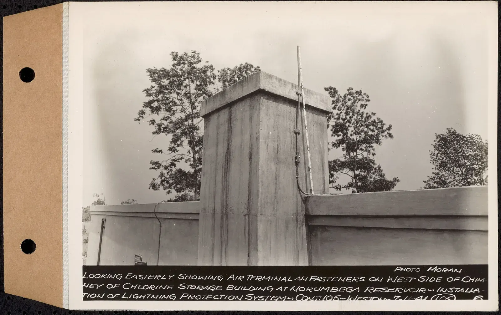
Start at the ridge. One terminal within 2 ft of each end, then fill in so no gap exceeds 20 ft (or 25 ft with 24 in rods). Then every projection that rises above the ridge or sits outside its zone: chimneys, dormers, cupolas, a steep gable on a wing, a tall plumbing vent, the antenna mast. Chimneys almost always get one, which is why the 1941 photo below looks so familiar. The roof conductor links all of them, and each terminal needs two paths to ground (LPI specification).
A one-story ranch with a simple ridge might need four to six terminals. A two-story house with a cross gable, two chimneys and a dormer might need a dozen. The count depends on the roof shape more than on the floor area.
Where terminals go on a flat commercial roof
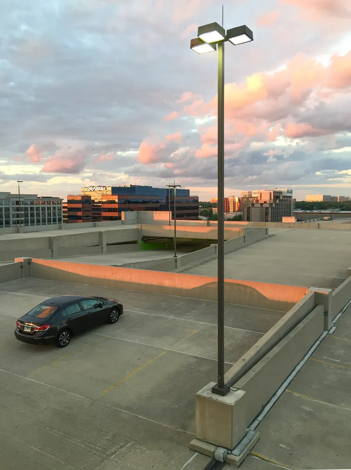
On a flat roof most of the terminals sit on the edge. The perimeter gets terminals within 2 ft of each corner and at 20 or 25 ft intervals along the parapet. Once the roof passes 50 ft in length or width, the interior gets a grid at up to 50 ft spacing (UL guide). Then the equipment: rooftop HVAC units, exhaust fans, skylights, signage, screen walls and light poles each need to sit inside a terminal’s zone or be bonded in as a strike termination device. On the parking structure in the photo below, the light poles themselves carry the terminals.
Membrane roofs change the mounting. Bases are adhered rather than screwed, with an adhesive the roofing manufacturer accepts, and any penetration goes through a flashed through-roof assembly so the warranty holds (LPI specification). That coordination belongs in the roofing spec. See our commercial lightning protection page for how these systems are scoped.
Metal bodies that stand in for terminals
LPI’s specification allows metallic bodies 3/16 in thick or more to serve as strike termination devices, provided they’re connected into the system with main-size conductors and bonding fittings that give at least 3 sq in of contact (LPI specification). Steel tank shells, heavy equipment housings and structural steel qualify. Thin metal doesn’t: a standing-seam roof panel or a sheet-metal duct will puncture, so it’s protected by terminals rather than used as one. The NWS standard says outright that metal roofing, siding, gutters and downspouts can’t substitute for conductors (NWSM 30-4106).
What inspectors find wrong with terminals
The terminal is the most exposed part of the system and the one most often disturbed. Common findings:
- Terminals removed during a re-roof and never put back, or put back without reconnecting the conductor.
- Bases pulled loose by wind or ice, leaving the terminal lying on the roof.
- A new rooftop unit, satellite dish or sign taller than the nearest terminal and outside its zone.
- Spacing stretched past 20 ft after a terminal was lost.
- Copper terminals on an aluminum conductor, or aluminum fittings in a chimney’s flue plume, corroding at the joint.
- Terminals over 24 in with no brace, bent over by a storm.
Any of these breaks the zone of protection. The rest of the system can be perfect and the roof still takes the hit. Our list of common problems found during inspections covers the conductor and ground faults that go with these.
Checking a roof
If you own a building with a system and can’t remember when the terminals were last looked at, or you’re planning rooftop equipment that might rise above them, contact Site Safe Lightning Protection for an inspection. For the rest of the hardware a terminal connects to, see lightning protection system components.
FAQ
What is the maximum spacing for lightning protection air terminals?
Under UL 96A and NFPA 780, 20 ft between terminals that are at least 10 in tall, or 25 ft between terminals that are at least 24 in tall. On flat roofs larger than 50 ft in either direction, interior terminals may be spaced up to 50 ft apart with the perimeter still at 20 or 25 ft.
How tall does an air terminal need to be?
At least 10 in above the object or surface it protects. Taller terminals (24 in) buy wider spacing. Terminals over 24 in have to be braced at half their height. Where people walk on the roof, the NWS standard wants the tip at least 5 ft up.
Do air terminals have to be pointed?
No. A 2000 field study at New Mexico Tech found moderately blunt tips were slightly better strike receptors than sharp ones, and rounded tips are now common on new US systems. Existing pointed terminals remain acceptable.
What are air terminals made of?
Solid copper, copper alloy or electrical-grade aluminum, at least 3/8 in in diameter for copper and 1/2 in for aluminum. Stacks over 75 ft use Class II terminals of copper, copper alloy, stainless steel, titanium or monel, at least 5/8 in in diameter and 18 to 30 in tall.
Talk to Site Safe Lightning Protection about your property.
Frequently asked questions
What is the maximum spacing for lightning protection air terminals?
Under UL 96A and NFPA 780, 20 ft between terminals that are at least 10 in tall, or 25 ft between terminals that are at least 24 in tall. On flat roofs larger than 50 ft in either direction, interior terminals may be spaced up to 50 ft apart with the perimeter still at 20 or 25 ft.
How tall does an air terminal need to be?
At least 10 in above the object or surface it protects. Taller terminals (24 in) buy wider spacing. Terminals over 24 in have to be braced at half their height. Where people walk on the roof, the NWS standard wants the tip at least 5 ft up.
Do air terminals have to be pointed?
No. A 2000 field study at New Mexico Tech found moderately blunt tips were slightly better strike receptors than sharp ones, and rounded tips are now common on new US systems. Existing pointed terminals remain acceptable.
What are air terminals made of?
Solid copper, copper alloy or electrical-grade aluminum, at least 3/8 in in diameter for copper and 1/2 in for aluminum. Stacks over 75 ft use Class II terminals of copper, copper alloy, stainless steel, titanium or monel, at least 5/8 in in diameter and 18 to 30 in tall.
Sources
- UL: Lightning Protection Marking and Application Guide (2016, UL 96 and UL 96A requirements)
- Lightning Protection Institute: Specification, Lightning Protection Systems (PDF)
- Lightning Protection Institute: Lightning Protection Overview
- NWSM 30-4106 Lightning Protection, Grounding, Bonding, Shielding, and Surge Protection Requirements (National Weather Service, 2017)
- Wikipedia: Lightning rod (summary of Moore et al., 2000, Lightning Rod Improvement Studies, J. Applied Meteorology)
- NFPA 780, Standard for the Installation of Lightning Protection Systems, 2023 edition (NFPA document page, free read-only access)
- National Weather Service: Lightning Rods and Lightning Protection Systems
Image credits
- Slim metal air terminal mounted at the gable end of a roof with the roof conductor clipped along the ridge behind it. Photo: Lukas Beck / Wikimedia Commons (source), CC BY 4.0, resized.
- 1941 photograph of an air terminal and fasteners on the concrete chimney of a chlorine storage building at Norumbega Reservoir, Massachusetts. Photo: Massachusetts Metropolitan District Water Supply Commission, photo John B. Moran, via Digital Commonwealth / DPLA / Wikimedia Commons (source), Public domain.
- Top level of a concrete parking garage at dusk with a tall light pole topped by an air terminal and the conductor running along the deck. Photo: Michael Chusid / Wikimedia Commons (source), CC BY-SA 4.0, resized.