Grounding a House for Lightning: Ground Rods, Soil and Spacing
By Site Safe Lightning Protection 7 min read
Grounding a house for lightning means putting a grounding electrode at the bottom of every down conductor in the lightning protection system, then bonding that grounding system to the house’s electrical service ground. At minimum that’s two down conductors with two electrodes, sized and placed for the soil you have. One copper rod pounded in beside the meter doesn’t do it.
This is the part of the system nobody sees, and it’s the part most often done wrong on DIY and handyman jobs. Here’s what the standards ask for and how soil changes the job.
Why the electrical ground isn’t enough
Every house already has a grounding electrode for the electrical service. That ground is sized for fault current on household circuits. A lightning strike is a very different load. UL’s lightning protection guide says a strike can exceed 300,000 amps. The Lightning Protection Institute FAQ makes the same point: the ordinary electrical ground isn’t designed to handle lightning.
A lightning protection system gets its own grounding electrodes, one at each down conductor. They’re then bonded to the electrical service ground so the two systems sit at the same potential. Penn State’s engineering course describes it the same way: the lightning protection system uses its own grounding electrode system, bonded rather than shared. We explain the bonding side in grounding vs bonding in lightning protection.
How many ground rods does a house need?
The LPI model specification sets the basic rules:
- At least two down conductors on any structure, no matter how small.
- Down conductors spaced at an average of no more than 100 feet around the perimeter.
- A ground termination for each down conductor, suited to the soil.
- A ground loop that interconnects all ground terminals on any structure taller than 60 feet.
For a typical one- or two-story house, that usually means two to four down conductors at the corners, each with its own electrode. LPI’s overview says electrodes are preferably placed at the building corners and outer extremities, below the frost line where possible. The exact count depends on the footprint, the roof shape and where the down conductors can run.
Grounding electrode options and minimum sizes
UL’s Lightning Protection Marking and Application Guide lists the permitted electrode types for lightning protection:
| Electrode | Minimum requirement (UL guide) | When it gets used |
|---|---|---|
| Ground rod | ½ in. diameter, 8 ft long; copper-clad steel, solid copper or stainless steel; extends at least 10 ft into the earth, below frost line where possible | Default choice where the soil is deep enough to drive |
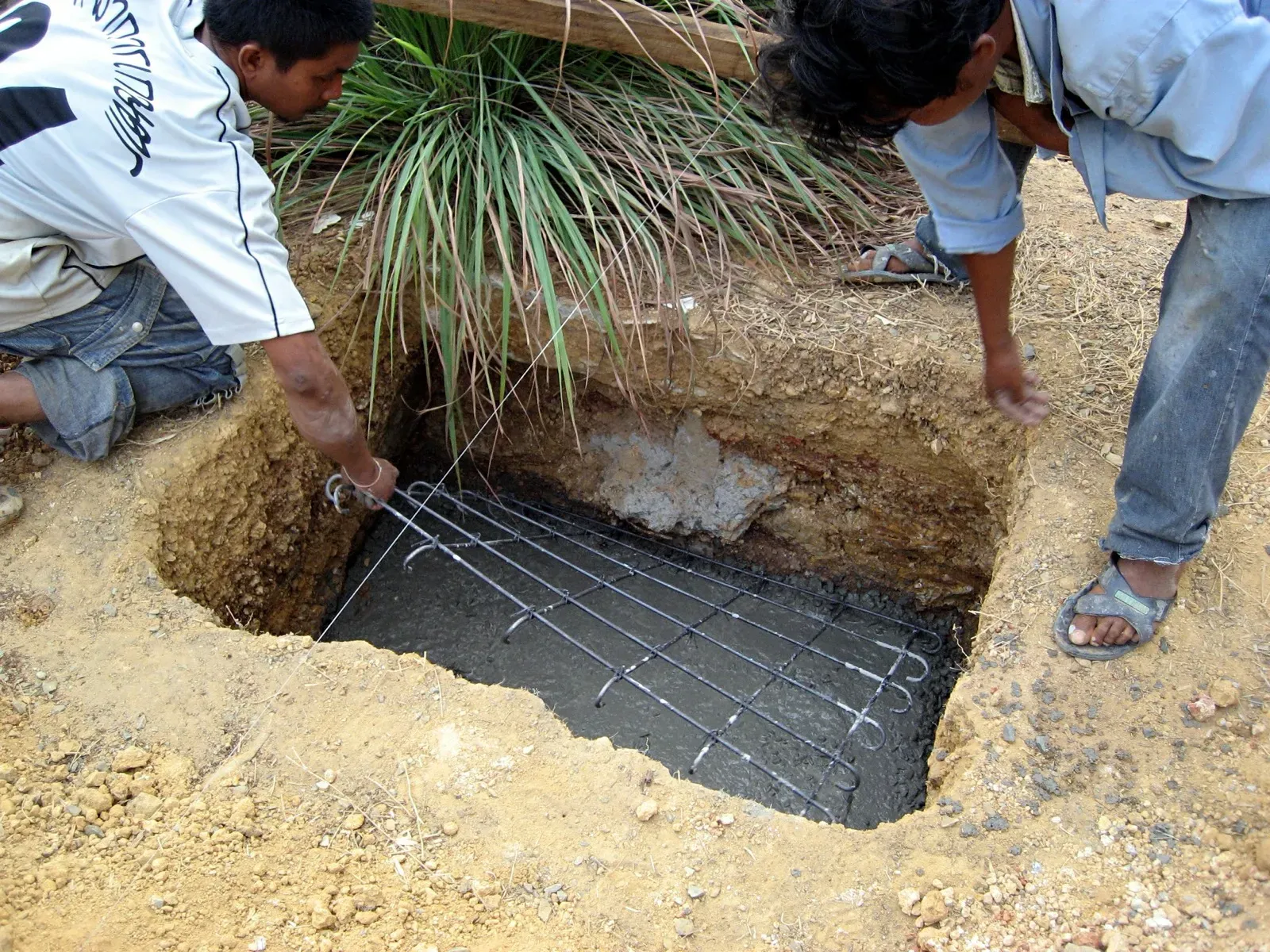
| Concrete-encased electrode | New construction only; 20 ft of main-size conductor, or at least 20 ft of #4 (½ in.) rebar, in at least 2 in. of concrete | New homes, poured during the footing pour |
| Ground ring | Main-size conductor buried at least 18 in. deep, encircling the structure | Rocky or shallow soil, or large and tall structures |
| Radial | Main-size conductor at least 12 ft long, buried at least 18 in. deep, run out from a down conductor | Shallow soil where rods won’t drive |
| Ground plate | At least 2 sq ft and 0.032 in. thick, buried at least 18 in. deep | Very shallow soil over rock |
The same guide adds that where topsoil is shallow, a combination of these methods is allowed. That’s the practical answer on many hillside and foothill lots.
Rocky, shallow and dry soil
Soil decides how hard grounding is. The National Weather Service facility standard (NWSM 30-4106) is blunt about it. Where crews find rock near the surface, shallow soil, permafrost, or soil with low moisture or mineral content, extra measures may be needed. Its facility grounding process starts with a site survey of rock formations, gravel deposits and soil types, plus soil resistivity tests at several distances from the building.
A homeowner doesn’t need a weather-station grounding design. The lesson carries over, though:
- If a rod won’t drive, don’t cut it off at 4 feet and call it done. Switch to radials, a ground ring or plates at the 18-inch depth the UL guide allows, or combine methods.
- On a rocky or shallow lot, expect the installer to walk the lot, look at grade and drainage, and possibly dig test holes before quoting.
- In dry soil, resistance to earth goes up. Spreading the current through more electrodes, a ring or radials helps.
Soil conditions change a lot from lot to lot. Rocky foothill lots, caliche, clay that shrinks and swells, and sandy river-bottom soil all behave differently. An installer should look at your site rather than quote a standard number of rods by phone.
Spacing and placement details that matter
- Rod spacing. NWSM 30-4106 calls for rods spaced at least twice the length of a single rod (for example, 10-foot rods about 20 feet apart). Rods driven close together share the same soil and add little.
- Depth of the top. The same NWS standard puts the tops of ground rods at least 1 foot below grade. Burial protects the connection from mowers and edgers.
- Distance from the foundation. Grounding electrodes generally go a short distance out from the footing, not tight against it. Your installer will set this from the standard and the site.
- Aluminum stays out of the dirt. UL’s guide says aluminum components can never contact the earth, and bimetallic fittings can’t be installed within 18 inches of grade. If your roof system is aluminum, the transition to copper happens above that line.
- Protection at grade. The LPI specification calls for guards on down conductors exposed to damage, up to 6 feet above grade.
Why one DIY rod falls short
The usual DIY setup is one air terminal, one cable and one rod. It misses on almost every count:
| DIY setup | What the standards expect |
|---|---|
| One down conductor | At least two, averaging no more than 100 ft apart |
| One short rod, often not fully driven | ½ in. × 8 ft rod extending at least 10 ft into the earth, or an allowed alternative |
| Rod not bonded to the electrical ground | Bonded to the service grounding electrode system with main-size conductor |
| Copper clamp on galvanized or aluminum | Listed fittings only. Copper isn’t installed on aluminum or external galvanized surfaces |
| No record of where the rods are | Documented layout, so the grounds can be tested later |
A system with one path to ground and no bond to the house’s other grounds can make side flash more likely, not less.
Test wells and checking the ground later
Electrodes are buried, so the only way to know they still work is to test them. NWSM 30-4106 allows an access well at a ground rod: a pipe or box with a removable cover so the electrode can be checked once the building is in use. NFPA 780 and LPI-175 recommend a visual inspection every year and a full inspection with testing every 3 to 5 years, including checks on the ground electrodes. We cover how the measurement works in fall-of-potential testing.
Owner’s checklist before you hire
- Ask how many down conductors and grounding electrodes the design includes, and where they go.
- Ask what electrode type they’ll use if rods won’t drive on your lot.
- Confirm the system will be bonded to the electrical service ground, water and gas piping.
- Ask for a drawing that shows electrode locations.
- Ask whether they’ll install a test well or other access for future testing.
Talk to us about your house
Site Safe Lightning Protection installs and inspects lightning protection systems for homes, commercial buildings and oil and gas facilities. If you’re planning a system or want an existing one checked, contact Site Safe Lightning Protection or start on our residential lightning protection page. Industrial owners can read the role of grounding systems in oil and gas lightning protection.
Talk to Site Safe Lightning Protection about your property.
Frequently asked questions
How do you ground a house for lightning?
Each down conductor of the lightning protection system ends at its own grounding electrode: a rod, ring, radial, plate or concrete-encased electrode. Every house has at least two. The whole grounding system is then bonded to the electrical service ground and to metal water and gas piping.
How deep does a lightning ground rod need to go?
UL's guide calls for a rod at least ½ inch in diameter and 8 feet long, extending at least 10 feet into the earth and below the frost line where possible. Where rods can't be driven, buried rings, radials or plates at least 18 inches deep are permitted.
Can I use my electrical ground rod for a lightning rod?
Not as the only ground. A lightning protection system needs its own electrodes at each down conductor. Those electrodes must then be bonded to the electrical service grounding system.
What is a ground ring?
A main-size conductor buried at least 18 inches deep that encircles the building and ties all the grounding electrodes together. It's common where soil is shallow or rocky, and the LPI specification requires a ground loop on structures over 60 feet tall.
How many ground rods does a lightning protection system need?
At least one per down conductor, and every structure needs at least two down conductors. Larger houses need more, at an average spacing of no more than 100 feet around the perimeter.
Sources
- NFPA 780, Standard for the Installation of Lightning Protection Systems, Annex D: Inspection and Maintenance (NFPA)
- LPI-175, Standard for the Design, Installation and Inspection of Lightning Protection Systems (Lightning Protection Institute)
- Lightning Protection Marking and Application Guide (UL, 2016)
- Lightning Protection Systems Specification (Lightning Protection Institute)
- Lightning Protection Overview (Lightning Protection Institute)
- NWSM 30-4106 Lightning Protection, Grounding, Bonding, Shielding, and Surge Protection Requirements (National Weather Service, 2017)
- Grounding and Lightning, AE 868 (Penn State)