The Fall-of-Potential Test: How Lightning Protection Grounds Are Measured
By Site Safe Lightning Protection 6 min read
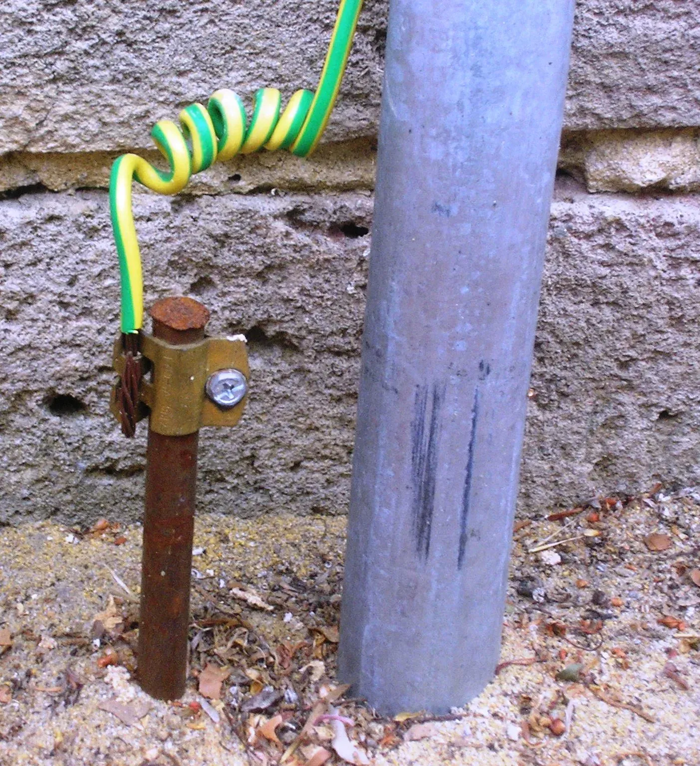
A fall of potential test measures how well a ground electrode is connected to the earth around it. The tester pushes a known current from the electrode to a stake driven some distance away, measures the voltage at a second stake placed in between, and divides voltage by current to get resistance in ohms. It’s the standard three-point method, and when it’s set up correctly it gives a reliable number for one electrode or a small group of them.
For a lightning protection system, that number is one piece of a bigger picture. This article explains how the test works in plain terms, how a technician knows the reading is good, and what to do with the result.
Why ground resistance matters for lightning protection
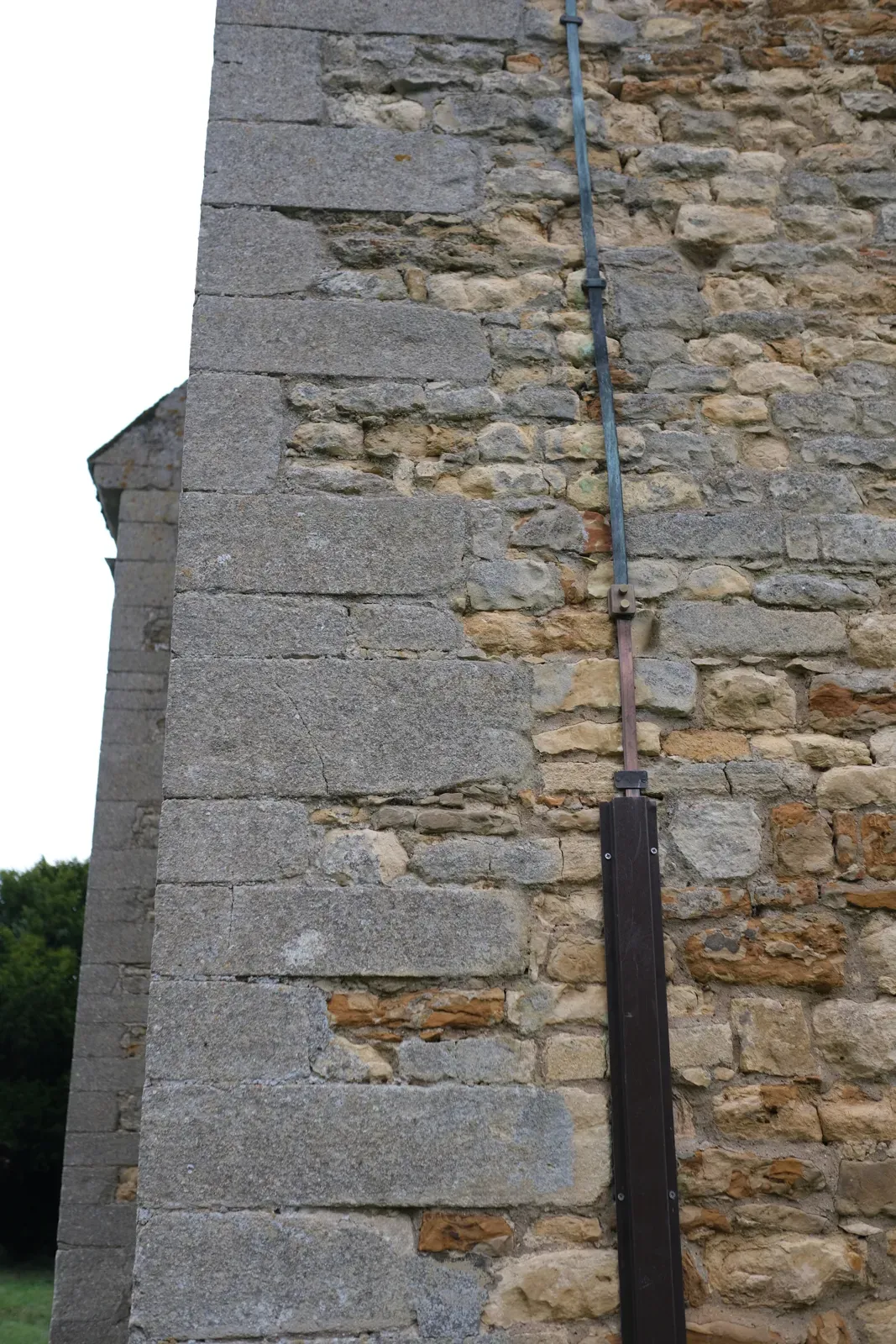
A lightning protection system has five parts: strike termination devices on the roof, conductors, bonding, grounding electrodes and surge protection. The Lightning Protection Institute describes the grounding electrode system as the part that has to move lightning current away from the structure and its contents. If a ground rod has corroded, been cut by a trencher, or was never driven deep enough, the current looks for another way down, and that’s when side flashes and fires happen.
You can’t see a ground electrode once it’s installed. Testing is how you find out if it still works.
How the fall-of-potential test works
The method uses three points in a straight line:
- The electrode under test (E). This is the ground rod or ground system you’re measuring.
- The current stake (H or C). An auxiliary stake driven well away from the electrode. The tester drives a known current between E and this stake.
- The potential probe (S or P). A second stake placed between the two. The tester measures the voltage between E and this probe.
Resistance is voltage divided by current (Ohm’s law). Fluke’s guide puts it simply: the tester generates a known current and measures the voltage drop to calculate resistance.
Where the stakes go
Every electrode has a “sphere of influence,” a zone of soil around it that the current flows through. If the probe sits inside that zone, or inside the current stake’s zone, the reading is wrong. Fluke stresses that the probe must be placed outside the sphere of influence of the electrode being tested.
Fluke gives these starting distances based on how deep the electrode goes:
| Electrode depth | Inner stake (probe) | Outer stake (current) |
|---|---|---|
| 2 m (about 6.5 ft) | 15 m (about 49 ft) | 25 m (about 82 ft) |
| 3 m (about 10 ft) | 20 m (about 66 ft) | 30 m (about 98 ft) |
| 6 m (about 20 ft) | 25 m (about 82 ft) | 40 m (about 131 ft) |
| 10 m (about 33 ft) | 30 m (about 98 ft) | 50 m (about 164 ft) |
The 62% rule
The “62% rule” says to put the potential probe at about 62% of the distance from the electrode to the current stake. Metrel, a test-instrument maker, explains that the rule comes from IEEE 81-2012 Annex C and gives the figure as 61.8%. It assumes uniform soil, electrodes that behave like hemispheres, and enough distance between E and H. Metrel’s practical guide is that the current stake should be at least five times the diameter of the grounding system away.
Those assumptions break down on large grids, in layered soil, or where the electrode is connected to other grounds such as utility neutrals or overhead shield wires. In those cases the current through the electrode isn’t the same as the current through the far stake, and the simple method misleads.
How to tell if a reading is good
A single reading proves nothing. The check is to move the probe and measure again.
Fluke’s instruction is to move the inner stake 1 m (3 ft) in either direction and take fresh readings. If the result changes significantly (Fluke uses 30% as the warning sign), the stakes are still inside overlapping spheres of influence. Increase the distance between the electrode and the current stake and repeat until the readings settle.
If you plot readings at many probe positions, a good test shows a flat stretch in the middle of the curve. That plateau is the true resistance. No plateau means the stakes are too close together.
Disconnect first
For a lightning protection ground, the electrode being tested usually has to be isolated from the rest of the system during the test. Otherwise the tester measures the whole interconnected network, including the building’s electrical ground and anything bonded to it, and the reading says little about the one rod you care about. This is where test wells and accessible connection points earn their keep.
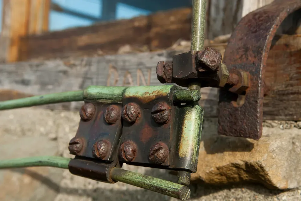
NFPA 780 added requirements in its 2017 edition for test and connection points on concrete-encased electrodes, specifically to allow periodic maintenance and testing of the ground system. A ground rod test well, a small box set flush with grade over the top of the rod and its clamp, does the same job for driven rods: the inspector can open it, check the connection, and disconnect for testing without digging.
What number is “good”?
This is where owners get conflicting answers, because different documents set different targets for different purposes:
| Source | What it says | Applies to |
|---|---|---|
| NEC 250.53(A)(2) | A single rod, pipe or plate electrode must be supplemented by another electrode unless it has 25 ohms or less to earth | Electrical service grounding |
| LLNL grounding engineering standard | Don’t exceed 5 ohms to earth in each grounding system, unless stated otherwise | That laboratory’s own facilities (an example of an owner spec) |
| NFPA 780 (2023) annex | Describes ground measurement techniques | Lightning protection systems |
The practical takeaway: if your specification, insurer or engineer gives you a target, that’s the number to test against. If nobody has set one, the useful comparison is against the system’s own earlier readings. A rod that tested at a certain value at installation and has doubled since is telling you something, regardless of where it falls against a code figure.
Record the date and recent weather with every test, and test at a similar time of year when you can, so later readings are compared under similar ground conditions.
When testing belongs in an inspection
NFPA 780 Section 1.7 says periodic inspections or testing are to be done at intervals set by the authority having jurisdiction. LPI’s overview describes inspection programs that include visual checks and continuity testing at five-year intervals.
Ground testing is worth adding:
- At installation, to set a baseline.
- During periodic inspections, especially on critical facilities.
- After excavation, trenching or paving near the building.
- After a known strike, or when a visual inspection finds damaged down conductors or corroded clamps.
- Before renewing a system certificate.
For the full scope of what an inspector checks, see what is tested during a lightning protection inspection and how often commercial systems should be inspected.
Common field problems
The test itself is simple. These are what usually go wrong:
- Stakes too close: the most common mistake, and the reason for the move-and-retest check.
- Electrode not isolated: the reading reflects the whole bonded network.
- Buried or paved-over connections: no test well, so nobody can reach the clamp.
- Parallel metal in the ground: buried pipes or fences between the stakes can skew results.
- No baseline: a single number with nothing to compare it to.
Our list of common problems found during inspections covers what turns up above ground.
Need your grounding checked?
If your building has a lightning protection system with no test records, or you’ve had excavation or a strike near the building, contact Site Safe Lightning Protection about an inspection that includes the grounding system. Reach us here.
Talk to Site Safe Lightning Protection about your property.
Frequently asked questions
What is the 3-point test for grounding?
It's another name for the fall-of-potential test: the electrode under test, a potential probe and a current stake in a straight line. The tester measures voltage and current between them and calculates resistance.
Why is the probe placed at 62% of the distance?
Under ideal conditions (uniform soil, hemispherical electrodes, enough spacing), placing the probe at 61.8% of the distance to the current stake gives the electrode's true resistance. The rule comes from IEEE 81-2012 Annex C.
What is an acceptable ground resistance?
It depends on the document you're working to. The NEC requires a single rod to be supplemented unless it measures 25 ohms or less. Owner specifications can be stricter; one national laboratory's standard sets 5 ohms. Ask your engineer or specifier which applies.
Do you need to disconnect a ground rod to test it?
For a fall-of-potential test on a single lightning protection electrode, usually yes. Otherwise the reading includes everything bonded to it. Test wells and accessible clamps make this practical.
How often should lightning protection grounds be tested?
NFPA 780 leaves the interval to the authority having jurisdiction. A baseline at installation, then testing during periodic inspections and after excavation or a strike, is a sensible approach.
Sources
- Fluke: Fall-of-Potential Measurement
- Metrel: Earth resistance measurement and the 62% rule (IEEE 81-2012 Annex C)
- NFPA 780, Standard for the Installation of Lightning Protection Systems, 2023 edition (NFPA document page, free read-only access)
- UpCodes: NEC 250.53 Grounding Electrode System Installation
- Lawrence Livermore National Laboratory: Grounding engineering standard (PEL-E-260525)
- Lightning Protection Institute: Lightning Protection Overview
Image credits
- Ground rod with a bolted clamp and green-yellow grounding conductor beside a house wall, the kind of electrode measured by a fall of potential test. Photo: F1jmm / Wikimedia Commons (source), CC BY-SA 3.0, resized.