Lightning Mast: When a Freestanding Mast Works Better Than Rods on the Roof
By Site Safe Lightning Protection 8 min read

A lightning mast is a freestanding pole or tower, topped with an air terminal, that takes the strike before it reaches the structure or equipment beside it. One mast can protect a small area. Two or more masts with an overhead wire strung between them form a catenary system, which covers a larger footprint. Masts make sense when you can’t or shouldn’t mount air terminals on the thing you’re protecting: fuel tanks and vents, explosives storage, open equipment yards, or launch pads. The trade-off is that a mast has to stand far enough away, and tall enough, that the strike stays on the mast.
Below: how masts are laid out and spaced, what published criteria require of the mast, and what to check on an existing one.
What a lightning mast is, and what a catenary system adds
The Department of Defense’s lightning criteria, UFC 3-575-01, define a catenary system as one or more overhead wires, each strung between masts, with the wire serving as both the strike termination device and the main conductor (UFC 3-575-01). A “mast system” in the same document means one or more masts without cross conductors.
| Layout | How it protects | Typical use |
|---|---|---|
| Air terminals on the structure | Points on the roof, ridge and edges, connected to down conductors on the building | Homes, offices, warehouses |
| Single mast | One tall pole with its own down conductors and grounding, set beside the structure | A small building, a vent, a single tank |
| Mast system | Several masts without wires between them | Groups of small structures, equipment pads |
| Catenary system | Overhead wires between masts; the wire takes the strike | Larger hazardous areas, launch pads, explosives facilities |
NFPA 780 counts masts and overhead ground wires as strike termination devices, like rods on a roof (NFPA 780). With an isolated mast, the current runs down the mast and into the ground beside the structure instead of across its roof.
When a mast is the better choice
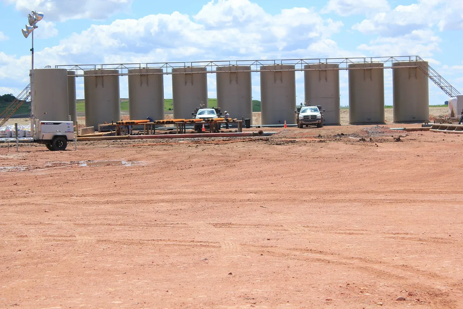
Equipment that vents flammable vapor
UFC 3-575-01 requires air terminals mounted on or next to equipment that exhausts hazardous vapors to stand at least 60 inches above it, with special supports. Past a certain point, a separate mast is simpler than a tall terminal bolted onto a vent stack. NFPA 780 has a chapter for structures containing flammable vapors, flammable gases or liquids that give off flammable vapors, which is the chapter tank batteries and other oil and gas equipment fall under (NFPA 780).
Explosives facilities
Military explosives facilities are designed to NFPA 780 Chapter 8 with a 100 ft (30.5 m) rolling sphere, unless the service says otherwise, and UFC 3-575-01 names mast or mast-with-catenary systems for permanently installed weapons system electronics (UFC 3-575-01).
Roofs that are hard to maintain
The Air Force section of the same document says adhesive fasteners for roof terminals can mean high maintenance and roof damage, and it suggests a mast or catenary system instead. Its stated goal is to use mast and catenary systems to cut maintenance, testing, repair and storm damage by up to 90%.
Open ground with no building to mount on
Fuel racks, pump pads and outdoor equipment don’t have a roof. A mast covers them from the side.
For a standard house or office, rods on the roof are almost always the cheaper and more practical answer. Masts are a site-specific design choice.
How the zone of protection is worked out
Mast height and spacing come from the rolling sphere method. You imagine a sphere rolled over and around the masts and wires; anything the sphere can’t touch is protected. For ordinary structures NFPA 780 caps the striking distance at 150 ft (45 m), which you can read about in our article on the rolling sphere method. Explosives facilities use the smaller 100 ft sphere noted above, which means the masts need to be taller or closer together for the same coverage.
UFC 3-575-01 requires the designer to prove the coverage on paper. For wooden mast and catenary systems, the rolling sphere must be shown valid in a drawing based on pole heights and wire heights. Ask for that drawing with any mast proposal so you can see whether the coverage reaches every piece of equipment you care about.
How far the mast has to stand from the structure
An isolated mast only works if the strike can’t jump from the mast or its down conductor to the structure. That jump is called a side flash. NFPA 780 has a formula for the minimum separation, and Mitchell Guthrie, a former NFPA 780 chair, lists what goes into it: the height of the conductor above the nearest bond, the material in the gap (air counts as 1, while concrete, brick and wood count as 0.5), and how many down conductors share the current (Guthrie et al., ATIS 2022). More down conductors split the current and shorten the required distance.
If a mast can’t be placed far enough away, the usual answer is to bond. UFC 3-575-01 lets military projects use the 6 ft (1.83 m) bonding rule from UL 96A in place of NFPA 780’s side flash calculation. Either way, the gap between a mast and a tank or building is part of the design.
What the mast itself needs
Most of the published detail on mast construction comes from UFC 3-575-01. It’s written for military sites, but it’s a useful benchmark for anyone writing a spec (UFC 3-575-01):
| Item | UFC 3-575-01 requirement |
|---|---|
| Steel masts up to 40 ft (12.2 m) | Single-section design |
| Metal wall thinner than 3/16 in. (4.8 mm) | Needs down conductors, placed as near 180 degrees apart as possible, run and bonded on the outside of the mast |
| Loads | Design for wind and ice on the mast and any overhead wires; provide damping per the manufacturer |
| Foundations | Anchor bolts in poured concrete, a stub set in concrete, or (for corrosion-resistant steel where soil allows) set directly in earth |
| Steel masts in a catenary | Rated for transmission/distribution line use, because the wire pulls sideways at the top |
| Wooden masts | Air terminals and two paths to ground; catenary poles need a heavier pole class |
| Nonconductive poles | Metal air terminals and two bare copper down conductors of at least 1/0 AWG, about 180 degrees apart and never inside the pole |
Structures taller than 75 ft fall into NFPA 780’s Class II material sizes, so tall masts and towers need heavier conductors than a house does (Guthrie et al.).
Grounding a mast or catenary system
Each down conductor ends at a grounding electrode or a ground ring. UFC 3-575-01 notes that NFPA 780 ground rods are 5/8 in. by 8 ft, and it recommends a ground rod in a test well between a down conductor and the ring, so the down conductor stays grounded if the ring is ever cut. Where a site needs a dedicated ground ring for a catenary system, that ring goes at least 3 ft (914 mm) outside the inner ring, and the two rings are bonded together in at least two places.
UFC 3-575-01 also requires bonding equipment and subsystems into a single grounding system for the facility, so the mast’s ground and the plant’s ground can’t sit at different voltages during a strike.
A real example: Launch Pad 39B
The best-documented mast and catenary system in the US is at NASA’s Kennedy Space Center. From the first shuttle launch in April 1981, Pad 39B was protected by a catenary wire running north to south, held up in the middle by an insulating mast. Construction of a replacement began in 2007: three towers supporting a catenary wire system with nine downleads, with the wire array installed in December 2009 (Mata et al., NASA).
NASA’s photo record of the build says each tower is 500 ft tall with a 100 ft fiberglass mast on top supporting the wire, and that the taller system was needed for the Ares I rocket, which stood higher than the shuttle (NASA image KSC-2009-1573). An oil and gas site uses the same idea at a much smaller scale, keeping the strike on the masts and wires and off the tanks.
Masts at oil and gas sites in Colorado, Texas and Oklahoma
Well pads, tank batteries and compressor stations in the region often sit alone on open ground. Tanks and vents can’t always carry air terminals, and some equipment gets moved or replaced. Masts and overhead wires let a designer protect the area without drilling into tanks or hanging terminals on a vent. Our guide to tank battery lightning protection covers the bonding and grounding side of those sites.
Checklist for an existing mast or catenary system
Walk it at least once a year and after any severe storm:
- Mast is plumb, guy wires (if any) are tight, and nothing has shifted at the base.
- Foundation concrete isn’t cracked; anchor bolts and stubs aren’t rusting through.
- Down conductors are attached along their full length and run on the outside of the mast.
- Overhead wires haven’t sagged closer to tanks, vents or buildings than the original drawing shows.
- Connections at the ground ring and test wells are tight and not corroded.
- New equipment added since the original design still sits inside the drawn zone of protection.
- Wooden poles show no rot at grade.
If you can’t find the original design drawing, that’s the first thing to fix.
Talk to Site Safe Lightning Protection
Site Safe Lightning Protection installs lightning protection systems for oil and gas facilities and commercial sites and inspects existing systems. Colorado, Texas and Oklahoma are the areas listed on our site. If you’re weighing a mast or catenary layout for a tank battery, vent or equipment yard, see our oil and gas lightning protection services or contact Site Safe Lightning Protection.
Talk to Site Safe Lightning Protection about your property.
Frequently asked questions
What is a lightning mast?
A freestanding pole or tower with an air terminal on top, set beside a structure so that lightning strikes the mast instead. It has its own down conductors and grounding. Several masts with wires strung between them make a catenary system.
How tall does a lightning mast need to be?
There's no single height. It depends on the area to be protected, the distance from the mast, and the rolling sphere radius used: 150 ft for ordinary structures under NFPA 780 and 100 ft for military explosives facilities under UFC 3-575-01. The designer shows the coverage on a drawing.
What is a catenary lightning protection system?
One or more overhead wires strung between masts. The wire takes the strike and carries the current to the masts' down conductors and the ground. It covers a larger area than single masts and is used at explosives facilities and launch pads.
How far should a lightning mast be from a building or tank?
Far enough to prevent a side flash. NFPA 780 calculates the distance from the conductor's height above the nearest bond, the material in the gap and the number of down conductors. Where that distance can't be met, the structure is bonded to the system instead.
Are early streamer emission (ESE) masts allowed?
Not under NFPA 780, which excludes ESE systems from its scope. UFC 3-575-01 prohibits ESE air terminals and dissipation arrays on military projects.
Sources
- UFC 3-575-01 Lightning and Static Electricity Protection Systems, with Change 1 (2021), WBDG
- NFPA 780, Standard for the Installation of Lightning Protection Systems (NFPA document page)
- Guthrie, VanSickle, Morgan: The Application of NFPA 780 and IEC 62305 in the United States (ATIS PEG, 2022)
- Mata et al.: A New Comprehensive Lightning Instrumentation System for Pad 39B at the Kennedy Space Center (NASA NTRS, ICLP 2010)
- NASA image KSC-2009-1573: lightning towers on Launch Pad 39B (caption)
Image credits
- Aerial view of three lightning protection towers with masts around Launch Pad 39B at Kennedy Space Center. Photo: NASA / Kim Shiflett (source), Public domain (US gov).
- Three lightning masts on Launch Pad 39B rising above palmetto scrub across the turn basin at Kennedy Space Center. Photo: NASA / Matthew J. Porter (source), Public domain (US gov).